Emergency Broadcasting - Understanding the speaker line checker
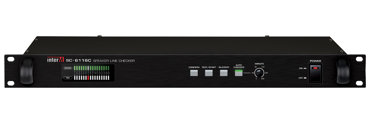
Resistance-based Speaker Line Checker - Inter-M's SC-6116C
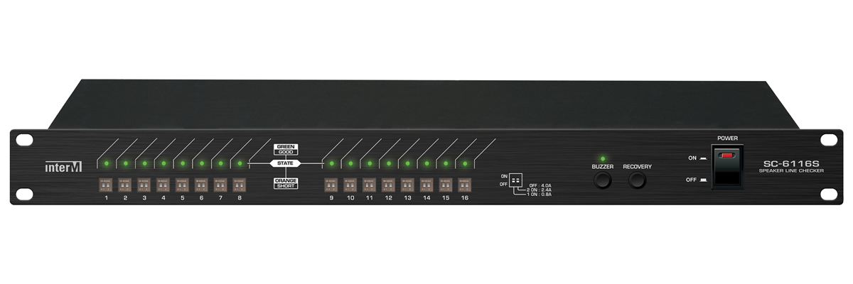
Current-based Speaker Line Checker - Inter-M's SC-6116S
Operating Principles of a Speaker Line Checker
There are two main methods to determine the health of a speaker circuit: resistance measurement and current measurement. These methods play a crucial role in accurately detecting whether a circuit is short-circuited.
The first method, resistance measurement, involves recording and analyzing the resistance values of the speaker circuit. In this approach, a standard resistance value for the circuit is set. If the actual measured resistance deviates from this preset range, the circuit is considered abnormal. This can indicate internal problems, such as faulty connections or damage to the speaker itself.
The second method, current measurement, involves real-time monitoring of the amount of current flowing through the speaker circuit. In this approach, a specific standard current value is established. If the actual measured current exceeds this threshold, the circuit is deemed abnormal. This can indicate the presence of a short circuit or other electrical issues, necessitating immediate action.
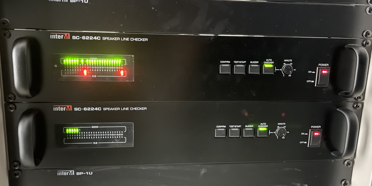
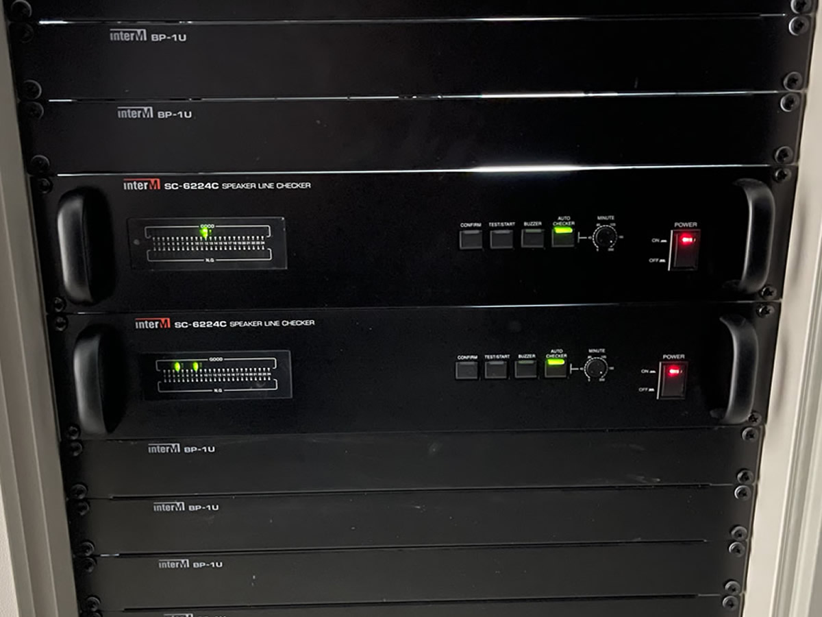
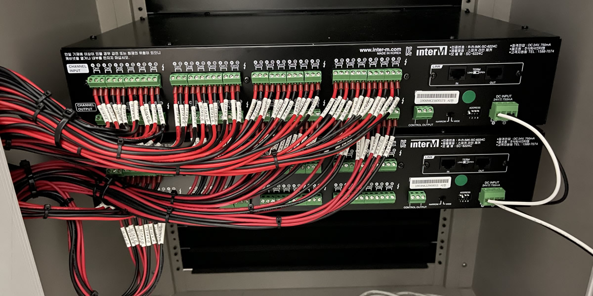
Speaker Circuit Status Display - Inter-M's SC-6224C
- Green LED: Indicates that the speaker is connected properly.
- Orange LED: Indicates a short-circuit condition in the speaker line.
- LED Off: Indicates that no speaker is connected to the line.
Causes and Solutions for Speaker Circuit Short Circuit
When a speaker circuit short circuits, it can result in no sound from all connected speakers, which can create difficulties in evacuating people during emergencies. Therefore, resolving short circuit issues is imperative.
One of the main causes of short circuits is the aging of speakers and volume controls due to prolonged use. In public address systems, high impedance speakers are used, which include transformers. Over time, the insulation of these transformers can deteriorate, leading to short circuits. Speakers and volume controls that have been in use for over 5 years should be replaced.
Speakers and volume controls are connected in a parallel structure. During installation, an accidental short circuit between the + and COM can occur due to wiring errors. Therefore, it's important to standardize cable types before work begins and define color-coded purposes to guide installers for correct installation. Always follow up with a verification process after installation. Such issues mainly occur post-installation.
Precautions When Installing a Speaker Line Checker
Resistance-based Speaker Line Checkers must be used within their operating range. For example, the Inter-M SC-6224 model can be used within a range of 20Ω to 3kΩ. When converted into speaker wattage, this corresponds to a usage range of 4W to 500W per channel. Below is the usage range for Inter-M products.
- SC-6224 : 20Ω~3kΩ (4W~500W)
- SC-6224C : 33.3Ω~10kΩ (1W~300W)
- SC-6116C : 125Ω~10kΩ (1W~80W)
Current-based Speaker Line Checkers should be set and used according to the capacity of the power amplifier. Please use them within the following range.
- 0.8A (Recommended for amplifiers above 120W)
- 2.4A (Recommended for amplifiers above 300W)
- 4.0A (Recommended for amplifiers above 400W)
Please use flexible stranded wires for cables connected to the equipment. Using stiff tray cables directly on the equipment can increase the risk of connectors becoming detached during inspection.
Speaker Line Checker connected with KIV stranded wire cable