Direct Box Recommendations and Selection Guide
Are you understanding and using impedance bridging?
If you properly understand the principles of impedance bridging and use a direct box, you can achieve better sound quality and efficient signal transmission when connecting high-impedance instruments or pickups to a mixer. Understanding the importance of a direct box and selecting the right product leads to more effective usage.
Why is a Direct Box Needed?
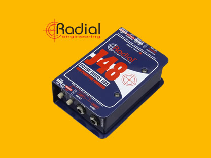
A direct box (DI box) is necessary to safely transmit audio signals, reduce signal loss, and address noise issues. A direct box converts high-impedance (High-Z) signals to low-impedance (Low-Z) signals, allowing for safe transmission to a mixer or audio interface. This prevents signal distortion and preserves audio quality, especially when signals travel through long and complex cable paths.
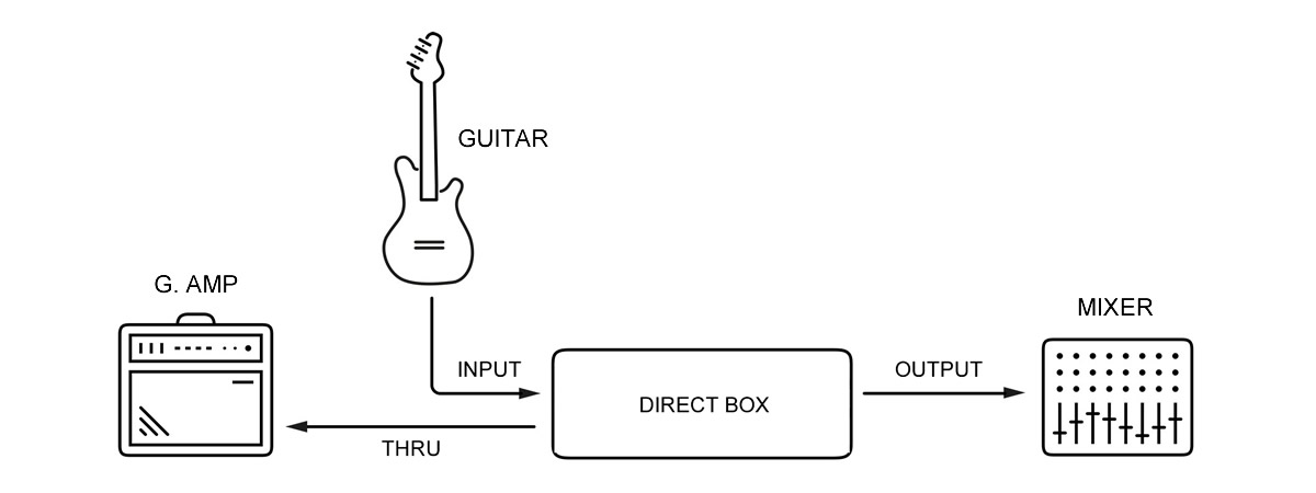
How to Connect a Direct Box
The Role of a Direct Box
A direct box performs various functions depending on the product, helping to maintain audio quality and reduce noise.
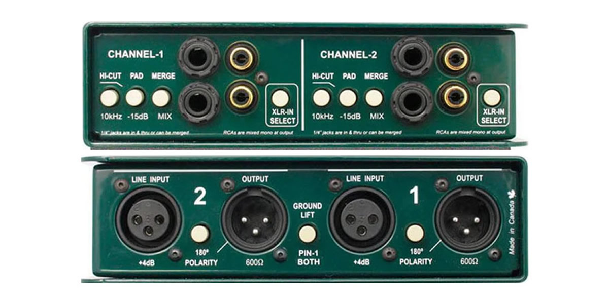
Direct Box Functions
- Impedance Conversion
- Balanced Signal Conversion
- Parallel Output
- Hum Noise Removal (Ground Lift)
- Attenuate Signal Level (Pad)
- Low/High-Frequency Noise Removal (Filter)
- Phase Inversion
The Impact of Direct Box Quality on Tone
The quality of a direct box greatly influences the tone, depending on the materials and design of its transformer. High-end DI boxes feature high-quality transformers that minimize noise and reduce signal distortion, preserving the original tone.
On the other hand, low-cost DI boxes may introduce more distortion and high-frequency loss. Therefore, using a high-quality direct box is essential in studio or professional live environments.
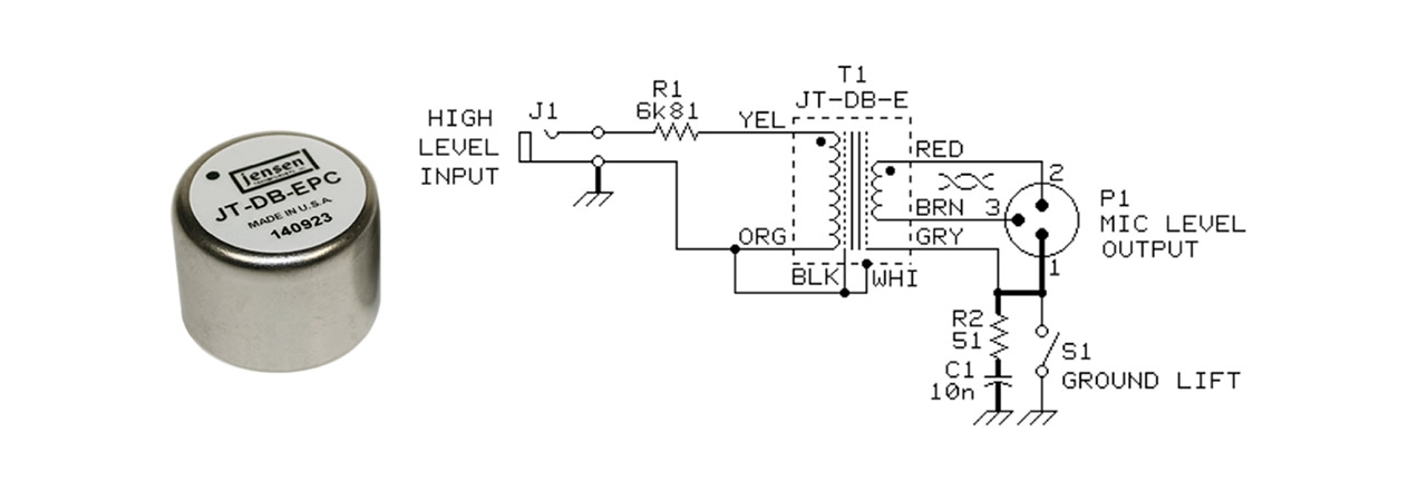
Jensen Transformers Used in High-Quality Direct Boxes
Piezo Pickups with Very High Output Impedance
Piezo pickups typically have very high output impedance, which can lead to signal loss and high-frequency roll-off when connected directly to a standard DI box.
Therefore, it is important to use a DI box with an input impedance of 3MΩ or higher. Some DI boxes are specifically designed for piezo pickups to address these issues.
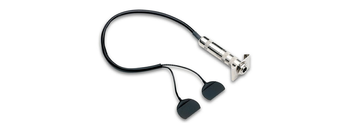
Fishman BP-100 Piezo Pickup Mounted on Bridge

Piezo Pickup Installed on Double Bass
Impedance Bridging and Loading Between Signals
The reason input impedance should be higher than output impedance is to minimize voltage loss during signal transmission and ensure smooth signal delivery. To understand this, let’s explore the basic principles of electrical signal transmission.
An electronic signal consists of current and voltage, and the ratio between output and input impedance significantly affects signal transmission as the signal moves from output to input.
When the output impedance is low and the input impedance is high, minimal voltage drop occurs on the input side during transmission, resulting in more stable and complete signal transfer. This is called impedance bridging, and it is the preferred approach in most audio equipment.
In contrast, impedance loading occurs when the input impedance is similar to or not sufficiently higher than the output impedance, leading to signal loss.
If the input impedance is lower or similar to the output impedance, significant voltage drop occurs, weakening the signal strength and quality. Sending a signal from low output impedance to high input impedance ensures that even high-frequency ranges are transmitted without loss. This results in clean and distortion-free signal delivery.
When the high-frequency components of an audio signal are lost, the sound quality may feel dull. Impedance bridging minimizes such loss, and the following formula can be used to calculate the loss:
\( V_{\text{out}} = V_{\text{in}} \times \frac{Z_{\text{in}}}{Z_{\text{out}} + Z_{\text{in}}} \)
- Output impedance is \( Z_{\text{out}} \), input impedance is \( Z_{\text{in}} \).
- When \( Z_{\text{out}} \) and \( Z_{\text{in}} \) are in series, total impedance is \( Z_{\text{out}} + Z_{\text{in}} \).
- Voltage \( V_{\text{in}} \) divides across output and input impedances.
- Final output voltage \( V_{\text{out}} \) is calculated by the voltage division formula.
Calculating Impedance Bridging and Loading
Here, we will calculate examples to compare voltage loss in cases where impedance bridging occurs versus cases where loading occurs due to insufficient impedance matching.
Impedance Bridging (Output 100Ω, Input 10kΩ):
\( V_{\text{out}} = V_{\text{in}} \times \frac{Z_{\text{in}}}{Z_{\text{out}} + Z_{\text{in}}} \)
\( = 1 \times \frac{10000}{100 + 10000} \approx 0.990 \; \text{V} \)
The output voltage is 0.99V, with almost no signal loss.
Impedance Loading (Output 600Ω, Input 600Ω):
\( V_{\text{out}} = V_{\text{in}} \times \frac{Z_{\text{in}}}{Z_{\text{out}} + Z_{\text{in}}} \)
\( = 1 \times \frac{600}{600 + 600} = 0.5 \; \text{V} \)
The output voltage is reduced to 0.5V, resulting in significant signal loss.
By calculating the output voltage, the voltage difference can be converted to dB. The dB voltage difference can be calculated using the following formula:
\( dB = 20 \cdot \log_{10} \left( \frac{0.990}{0.5} \right) \approx -5.93 \, \text{dB} \)
Converting the output voltage reduction to decibels shows a loss of approximately 5.93 dB.
Basic Values Required for Impedance Calculation
While there may be slight variations depending on the product, the following values are generally used as a baseline.
- Instrument Output Impedance \((Z_{\text{inst}})\) : \(10\,k\Omega\)
- Piezo Pickup Output Impedance \((Z_{\text{piezo}})\) : \(1\,M\Omega\)
- Piezo Direct Box Input Impedance \((Z_{\text{PZDI-in}})\) : \(10\,M\Omega\)
- Direct Box Input Impedance \((Z_{\text{DI-in}})\) : \(1\,M\Omega\)
- Direct Box Output Impedance \((Z_{\text{DI-out}})\): \(600\,\Omega\)
- Mixer Mic Input Impedance \((Z_{\text{mic-in}})\) : \(2\,k\Omega\)
- Mixer Line Input \((Z_{\text{line-in}})\) : \(10\,k\Omega\)
- Input Signal Voltage \((V_{\text{inst}})\) : \(1\,\text{V}\)
Impedance Calculation from Instrument Output to Audio Mixer Input
Voltage transmitted from instrument output to direct box input:
\( V_{\text{out}} = V_{\text{inst}} \times \frac{Z_{\text{DI-in}}}{Z_{\text{inst}} + Z_{\text{DI-in}}} \)
\( = 1 \times \frac{1,000,000}{10,000 + 1,000,000} \approx 0.990 \; \text{V} \)
\( \text{dB loss} = 20 \cdot \log_{10} \left( \frac{0.990}{1} \right) \approx -0.09 \, \text{dB} \)
Voltage transmitted from direct box output to audio mixer input:
\( V_{\text{mixer-in}} = V_{\text{DI-in}} \times \frac{Z_{\text{mixer-in}}}{Z_{\text{DI-out}} + Z_{\text{mixer-in}}} \)
\( = 0.990 \times \frac{10,000}{600 + 10,000} \approx 0.934 \, \text{V} \)
\( \text{dB loss} = 20 \cdot \log_{10} \left( \frac{0.934}{1} \right) \approx -0.59 \, \text{dB} \)
As shown in this example, impedance bridging (when input impedance is higher than output impedance) minimizes voltage loss.
Impedance Calculation When Using a Piezo Pickup with a Standard Direct Box
Piezo pickups have very high output impedance, so connecting them to a standard direct box with low input impedance can result in signal loss and degraded frequency response.
\( V_{\text{out}} = V_{\text{inst}} \times \frac{Z_{\text{DI-in}}}{Z_{\text{piezo}} + Z_{\text{DI-in}}} \)
\( = 1 \times \frac{1,000,000}{1,000,000 + 1,000,000} = 0.500 \, \text{V} \)
\( \text{dB loss} = 20 \cdot \log_{10} \left( \frac{0.500}{1} \right) \approx -6.02 \, \text{dB} \)
When a piezo pickup is connected to a standard direct box, the signal becomes weaker.
Impedance Calculation When Using a Piezo Pickup with a Dedicated Direct Box
When using a direct box with a 10 MΩ input impedance to handle the high output impedance of a piezo pickup, signal loss is minimized. This results in almost no voltage loss, allowing signal quality to be preserved.
\( V_{\text{out}} = V_{\text{inst}} \times \frac{Z_{\text{PZDI-in}}}{Z_{\text{piezo}} + Z_{\text{PZDI-in}}} \)
\( = 1 \times \frac{10,000,000}{1,000,000 + 10,000,000} \approx 0.909 \, \text{V} \)
\( \text{dB loss} = 20 \cdot \log_{10} \left( \frac{0.909}{1} \right) \approx -0.83 \, \text{dB} \)

